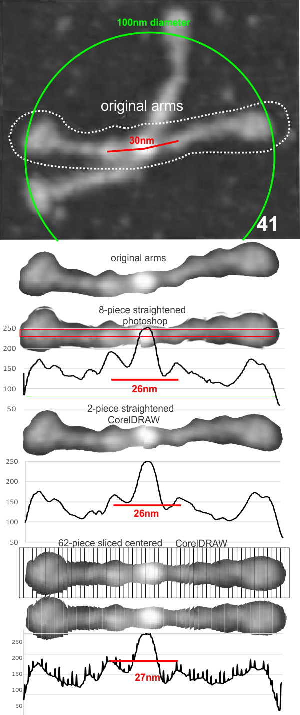
Dodecamers of SP-D can have arms that are arched. Trying to calculate the grey scale for curved objects is not straightforward. Below is a summary of several attempts to “straighten” the arms and provide an image where a sample of several pixels (in this case about 70 pixels in height) can be drawn through the center and capture the spots along the arms that are highlighted during the shadowing (or other) procedure.
At least two of the reasons for doing this are 1) to determine whether the extent of the central area where the arms are knit together in a bundle encompasses more than the N terminal region (that is: does it include some of the collagen like domain) and 2 whether that central region that is knit together includes a “bend” or other element in the AA sequence that could be used to predict how the fuzzy balls are joined at the center, whether a ring, or a wad (haha).
The techniques below include using three programs, photoshop, CordlDRAW and ImageJ, the first two were used to even out the arched arms, and the latter to create a LUT table for the grey scale (across an area of about 450 pixels (or 120+nm).
The procedure that I think is the most accurate, produces the least amount of “noise” and is the quickest to produce is as follows: The image (a dodecamer comprising mirrored monomers attached at N terminals) is opened in photoshop. A single set of two monomers (a right and left set) are cut in photoshop into a new layer. The lasso tool is used to isolate and copy vertical segments of the dimer which are systematically adjusted to be central in the length of the dimer. The image is flattened, exported as a tiff then opened in ImageJ where a 70 pixel wide rectangle is drawn the full length of the image. There Analyze and Plot Profile are applied. The grey scale lists are saved in excel and plotted as a line graph. The excel plot can be stretched lengthwise to fit the length of the original image thus the peaks and valleys can be measured against a dimension of 100nm.
The demonstration (middle images) here is just a cut and rotate of two halves of the selected dodecamer. Each half was rotated to create a relatively straight molecule. This only works on some opportune images. You can see the plot generated is almost identical to that produced with photoshop.
The third option didn’t work out that well, though it is the fastest. There are about 62 cuts in the image and each individual cut in the tiff file can be centered in one click. The problem with this method is that CorelDRAW actually eliminates some of the pixels at the cut line, thereby adding a lot of “noise” to the plots (see bottom plot). While the measurements remain valid and it appears to be the most accurate (because it points out most clearly that there is a second peak left and right of center from the N terminal of the dimer) it is surely ugly.
The best of all would be to find a way to use a grid to slice up the photoshop images. I guess I will have to figure that out.
Just for the record, the newest in today’s nanotechnology was invented by “life” a long long time ago, and the complex assembly of namomachines like surfactant fuzzy balls is a great model to use. While many think that they have invented something new… nope, this is not new. What will be fun to watch is the use of natures own innate immune inventions show up in the new molecules created through nanotechnology and their use in disease treatment. Just a step away.
